一.项目背景
本次实训项目旨在搭建一个复杂的企业网络拓扑,涵盖了多个核心技术领域包括交换机配置、动态路由协议(OSPF)、链路状态路由协议(ISIS)、边界网关协议(BGP)以及路由策略的实施。
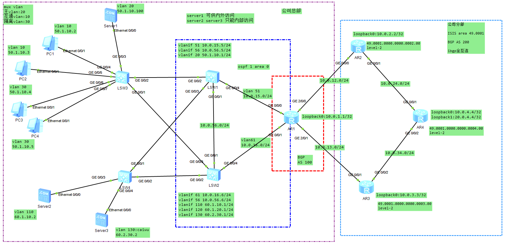
1.1交换机路由器基本配置:
配置设备名称和VLAN,确保各设备在拓扑图中的角色明确。
配置接口IP地址,以支持设备之间的通信。
LSW1与LSW3之间配置access端口;LSW1与LSW2之间配置trunk端口;
LSW1与LSW4之间配置trunk端口;LSW2与LSW3之间配置trunk端口;
LSW1与AR1之间配置access端口;LSW2与AR1之间配置access端口;
LSW2与LSW4之间配置trunk端口。
AR1:
sysname AR1
interface GigabitEthernet 0/0/0
ip address 10.0.15.1 24

interface GigabitEthernet 0/0/1
ip address 10.0.16.1 24


interface GigabitEthernet 2/0/0
ip address 10.0.12.1 24

interface GigabitEthernet 2/0/1
ip address 10.0.13.1 24

interface LoopBack 0
ip address 10.0.1.1 32
查看端口IP地址和端口状态信息:
display ip interface brief
interface LoopBack 0
ip address 10.0.1.1 32
AR2:
sysname AR2
interface GigabitEthernet 0/0/0
ip address 10.0.12.2 24


interface GigabitEthernet 0/0/1
ip address 10.0.24.2 24


interface LoopBack 0
ip address 10.0.2.2 32
AR3:
sysname AR3

interface GigabitEthernet 0/0/1
ip address 10.0.13.3 24


interface GigabitEthernet 0/0/2
ip address 10.0.34.3 24


interface LoopBack 0
ip address 10.0.3.3 32
AR4:
sysname AR4

interface GigabitEthernet 0/0/1
ip address 10.0.24.4 24

interface GigabitEthernet 0/0/2
ip address 10.0.34.4 24

interface LoopBack 0
ip address 10.0.4.4 32

interface LoopBack 1
ip address 20.0.4.4 32
LSW1:
sysname LSW1
vlan batch 10 20 30 51 56 110 120 130
interface Vlanif 20
ip address 50.1.10.1 24
interface Vlanif51
ip address 10.0.15.5 24
interface Vlanif 56
ip address 10.0.56.5 24
interface GigabitEthernet 0/0/1
port link-type trunk
port trunk pvid vlan 56
port trunk allow-pass vlan 2 to 4094

interface GigabitEthernet 0/0/2
port link-type access
port default vlan 20

interface GigabitEthernet0/0/3
port link-type trunk
port trunk allow-pass vlan 2 to 4094

interface GigabitEthernet0/0/4
port link-type access
port default vlan 51
LSW2:
vlan batch 10 20 30 56 61 110 120 130


interface Vlanif56
ip address 10.0.56.6 24

interface Vlanif 61
ip address 10.0.16.6 24

interface Vlanif 110
ip address 60.1.10.1 24


interface Vlanif 120
ip address 60.1.20.1 24


interface Vlanif 130
ip address 60.2.30.1 24
interface GigabitEthernet0/0/1
port link-type trunk
port trunk pvid vlan 56
port trunk allow-pass vlan 2 to 4094
interface GigabitEthernet0/0/2
port link-type trunk
port trunk allow-pass vlan 2 to 4094
interface GigabitEthernet0/0/2
port link-type trunk
port trunk allow-pass vlan 2 to 4094
interface GigabitEthernet0/0/4
port link-type access
port default vlan 61LSW3:
sysname LW3

vlan batch 10 20 30 110 120 130
interface GigabitEthernet0/0/1
 port link-type trunk
 port trunk allow-pass vlan 2 to 4094


interface GigabitEthernet0/0/2
 port link-type access
 port default vlan 20


interface GigabitEthernet0/0/3
 port link-type access
 port default vlan 20
 stp edged-port enable

interface GigabitEthernet0/0/4
 port link-type access
 port default vlan 10
 stp edged-port enable

interface GigabitEthernet0/0/5
 port link-type access
 port default vlan 10
 stp edged-port enable

interface GigabitEthernet0/0/6
 port link-type access
 port default vlan 30
 stp edged-port enable

interface GigabitEthernet0/0/7
 port link-type access
 port default vlan 30
 stp edged-port enable
LSW4:
vlan batch 10 20 30 110 120 130


interface GigabitEthernet0/0/1
 port link-type trunk
 port trunk allow-pass vlan 2 to 4094

interface GigabitEthernet0/0/2
port link-type trunk
port trunk allow-pass vlan 2 to 4094

interface GigabitEthernet0/0/3
port link-type access
port default vlan 110
stp edged-port enable

interface GigabitEthernet0/0/4
 port link-type access
 port default vlan 130
 stp edged-port enable
1.2 RSTP配置:
将LSW1设为根交换机,LSW2为备份根交换机,配置RSTP以实现快速链路故障恢复和环路消除。
开启bpdu防护,设置边缘端口和根保护,保证交换机在网络中稳定运行。
RSTP配置要求
LSW1、LSW2、LSW3、LSW4之间配置RSTP,LSW1为根交换机,LSW2为备份根交换机;
所有交换机开启bpdu防护,连接终端的端口设置为边缘端口;
LSW2:
interface GigabitEthernet 0/0/2
stp root-protection

interface GigabitEthernet 0/0/3
stp root-protection
LSW1:
interface GigabitEthernet 0/0/3
stp root-protection
所有交换机开启tc-bpdu保护,允许收到tc-bpdu报文后立即进行地址表项删除操作的最大次数为2次
LSW1:
stp mode rstp
stp instance 0 root primary
stp tc-protection
stp tc-protection threshold 2
LSW2:
stp mode rstp
stp instance 0 root secondary
stp tc-protection
stp tc-protection threshold 2
LSW3:
stp mode rstp
stp bpdu-protection
stp tc-protection
stp tc-protection threshold 2
LSW4:
stp mode rstp
stp bpdu-protection
stp tc-protection
stp tc-protection threshold 2
1.3 OSPF配置:
配置LSW1、LSW2和AR1之间的OSPF,确保在网络拓扑变化时能快速适应并更新路由信息。
配置区域间简单认证,增加网络安全性。
LSW1、LSW2、AR1之间配置ospf,当网络拓扑发生改变,设备需要立即泛洪新的LSA,收到新的LSA的设备立即进行路由计算;
配置区域间简单认证,认证密码:huawei;
LSW1在区域0仅声明10.0.15.0/24和10.0.56.0/24网段,其他网段采用导入直连路由的形式,并对导入的网段以B类网段汇总的方式声明;
LW1:
ospf 1 router-id 10.0.51.5
 asbr-summary 50.1.0.0 255.255.0.0
 import-route direct
 area 0.0.0.0
  authentication-mode simple plain huawei
  network 10.0.15.0 0.0.0.255
  network 10.0.56.0 0.0.0.255
LSW2在区域0仅声明10.0.16.0/24和10.0.56.0/24网段,其他网段采用导入直连路由的形式,并对导入的连续的直连路由以手工汇总的方式声明;
LW2:
ospf 1 router-id 10.0.16.6
 asbr-summary 60.1.0.0 255.255.224.0
 import-route direct
 area 0.0.0.0
  authentication-mode simple plain huawei
  network 10.0.16.0 0.0.0.255
  network 10.0.56.0 0.0.0.255
AR1:
ospf 1 router-id 10.0.1.1
 default-route-advertise
 area 0.0.0.0
  authentication-mode simple plain huawei
  network 10.0.15.0 0.0.0.255
  network 10.0.16.0 0.0.0.255
1.4 ISIS配置:
在AR2、AR3和AR4之间配置ISIS协议,根据要求配置router id和路由器类型,使得在大规模网络中可以实现高效的路由信息传递。
命令是在指定接口上启用ISIS协议,并将其加入到ISIS进程1中。通过在不同的Loopback接口上执行此命令,可以将这些接口加入到ISIS进程中,从而允许它们参与到ISIS的路由计算
AR2:
isis 1
 is-level level-2
 network-entity 49.0001.0000.0000.0002.00
 is-name AR2
interface GigabitEthernet 0/0/1
isis enable 1在AR2的g0/0/1和loopback0上启用Isis;
AR2:
interface LoopBack 0
isis enable 1
bgp 200
ipv4-family unicast
peer 10.0.4.4 next-hop-local
peer 10.0.12.1 default-route-advertise AR3:
isis 1
is-level level-2
network-entity 49.0001.0000.0000.0003.00
is-name AR3interface GigabitEthernet 0/0/2
isis enable 1
在AR3的g0/0/2和loopback0上启用Isis;
AR3:
interface LoopBack 0
isis enable 1
bgp 200
ipv4-family unicast
peer 10.0.4.4 next-hop-local
peer 10.0.13.1 default-route-advertise AR4:
isis 1
is-level level-2
network-entity 49.0001.0000.0000.0004.00
is-name AR4在AR4的g0/0/1、g0/0/2和loopback0、loopback1上启用Isis;
AR4:
interface LoopBack 0
isis enable 1
interface GigabitEthernet 0/0/1
 isis enable 1
interface GigabitEthernet 0/0/2
isis enable 1
interface LoopBack 1 (加入到到表中,才有路由)
isis enable 11.5 BGP配置
配置AR1、AR2、AR3之间的EBGP,以及AR2、AR3、AR4之间的IBGP,确保在不同自治系统之间和自治系统内部能够进行有效的路由信息交换。
向EBGP邻居宣告默认路由,并根据要求引入其他动态路由信息。
AR1:
bgp 100
 router-id 10.0.1.1
 peer 10.0.12.2 as-number 200
 peer 10.0.13.3 as-number 200
 #
 ipv4-family unicast
  network 10.0.1.1 255.255.255.255
  import-route ospf 1 route-policy caiwu
  peer 10.0.12.2 enable
  peer 10.0.13.3 enable
AR2:
bgp 200
 router-id 10.0.2.2
 peer 10.0.4.4 as-number 200
 peer 10.0.4.4 connect-interface LoopBack 0
 peer 10.0.12.1 as-number 100
#
 ipv4-family unicast
  undo synchronization
  import-route isis 1
  peer 10.0.4.4 enable
  peer 10.0.12.1 enable
AR3:
bgp 200
 router-id 10.0.3.3
 peer 10.0.4.4 as-number 200
 peer 10.0.4.4 connect-interface LoopBack 0
 peer 10.0.13.1 as-number 100
 #
 ipv4-family unicast
  undo synchronization
  import-route isis 1
  peer 10.0.4.4 enable
  peer 10.0.13.1 enable
AR4:
bgp 200
 router-id 10.0.4.4
 peer 10.0.2.2 as-number 200
 peer 10.0.2.2 connect-interface LoopBack 0
 peer 10.0.3.3 as-number 200
 peer 10.0.3.3 connect-interface LoopBack 0
 #
 ipv4-family unicast
  undo synchronization
  peer 10.0.2.2 enable
  peer 10.0.3.3 enable
1.6 路由策略:
在AR1、AR4上配置特定的路由策略,限制特定网段的路由传递,优化路由路径,提升网络效率和安全性。
AR1:
acl number 2000
rule 5 permit source 60.2.30.0 0.0.0.255AR1上配置路由策略caiwu,不允许60.2.30.0/24网段的信息传递到公司分部;
AR1:
route-policy caiwu deny node 1
if-match acl 2000
route-policy caiwu permit node 2AR1上配置路由策略MED,通过AR3到达20.0.4.4/32;
下路:AR1-AR2-AR4
route-policy MED permit node 10
if-match ip-prefix MED
apply cost 83

route-policy MED permit node 20AR1上配置路由策略MED,通过AR2到达20.0.4.4/32;
上路:AR1-AR3-AR4
route-policy MED1 permit node 10
if-match ip-prefix MED
apply cost 100

route-policy MED1 permit node 20
AR1:
bgp 100
ipv4-family unicast
import-route ospf 1 route-policy caiwu
peer 10.0.12.2 route-policy MED1 import
peer 10.0.13.3 route-policy MED import
配置IPv4地址前缀列表
AR1:
ip ip-prefix MED index 10 permit 20.0.4.4 32AR4:
acl number 2001
rule 5 permit source 60.1.0.0 0.0.31.255

route-policy as-path permit node 10
if-match acl 2001
apply as-path 100 additive

bgp 200
ipv4-family un
peer 10.0.2.2 route-policy as-path import
peer 10.0.2.2 next-hop-local
peer 10.0.3.3 next-hop-local
检查各个PC和service服务的IP
隔离vlan:mux vlan
主vlan:20
互通vlan:10
隔离vlan:30
LSW3:
vlan 20
mux-vlan
subordinate separate 30
subordinate group 10
interface GigabitEthernet 0/0/2
port mux-vlan enable
interface GigabitEthernet 0/0/3
port mux-vlan enable 验证
server1 可以内外PC访问服务器,server2和server3为内部PC访问服务器
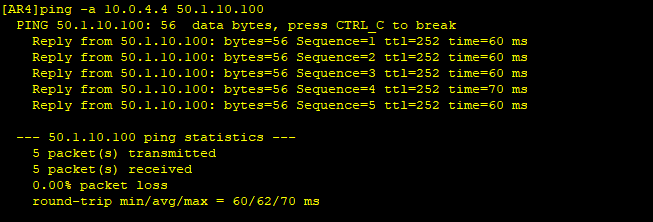
AR4 ping server1
display bgp routing-table 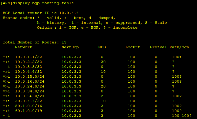
ping -a 10.0.4.4 50.1.10.100